Project name:- DTMF Cell Phone controlled Electrical appliances.
Objective:-
- To control our home and office electrical appliances using our cell phone.
- To control any electrical appliances using mobile phone without using a microcontroller.
- To Understand DTMF (Dual Tone Multi Frequency) technique.
Theory :-
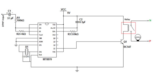
This home appliances control or home automation project also uses the same DTMF decoder circuit section with little modifications to control home and office electrical appliances. Just connect the cell phone headset (headphone) jack to the mobile phone and then mobile will control electrical appliances and electrical equipment through the DTMF key pad of the cell phone. Here we are controlling an electrical bulb using this circuit project but it can also control many electrical devices with some modifications using 4×16 decoder IC.
Circuit diagram of mobile controlled Electrical appliances:-
 Fig:-circuit diagram of mobile automation
Components required for home automation:-
- Power Supply.
- DTMF decoder IC (MT-8870).
- Resistors (100kΩ×2; 330kΩ).
- Capacitors 0.1µF; 10 µF(50v); 22pf ×2 .
- Crystal oscillator (3.579545MHz).
- BC547 Transistor.
- 6V relay.
Working Principle of home automation electronic project:-
- Our project uses M-8870 DTMF decoder IC which decodes tone generated by the keypad of cell phone.
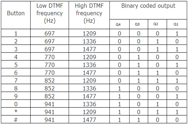
- When we press any key on mobile phone while call is in progress, the other person will hear some tones corresponding to the keys pressed. These tones are based on the DTMF (Dual Tone Multi Frequency) technology.
- Data is transmitted as pairs of tones. The receiver detects the valid frequency pair and gives the appropriate BCD code as the output of the DTMF decoder IC.
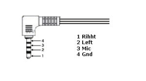
- DTMF signal can be tapped directly from the microphone pin of cell phone device.
- Cut the microphone wire and we will be able to see 4 wires. Among these wires we need only 2 wires- Ground and Right as shown in figure.
- Select the right wire and connect it as the DTMF input to the decoder circuit. Ground should be connected to common ground of the circuit.
- The signals from the microphone wire are processed by the DTMF decoder IC which generates the equivalent binary sequence as a parallel output of Q1, Q2, Q3, and Q4.
- At Q1 When we press and release any of the keys among 1, 3, 5, 7, 9 and *, the DTMF decoder IC generates a high pulse which acts as a clock .
- The output Q1 is connected to the relay driver circuit; this output energizes the relay coil through BC547 transistor and turns ON the bulb that is connected at the normally open terminal of relay circuit.
Table showing DTMF Low and High frequency tones and decoded output:-
Discussion:-
Each key pressed on the keypad generates two tones of particular frequencies, so a voice or a random signal cannot mimic DTMF signaling tones. One tone is generated from a High DTMF frequency group of tones and the other from Low DTMF frequency group thus the name ‘Dual Tone’. This is the basic of using dual tone in DTMF communication. These two tones will be distinctive and different from tones of other keys. So there is a low and high frequency associated with a button, it is essentially the sum of two waves is transmitted.
ফেসবুক এ আমি : S@G@R

